YiRadar
Integration guide · Reviewed resource
Reviewed by Mr. Wang, YiRadar Engineering · · Review standard
Radar Sensor Mounting Height: A Practical Engineering Guide
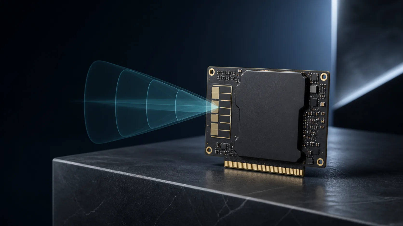
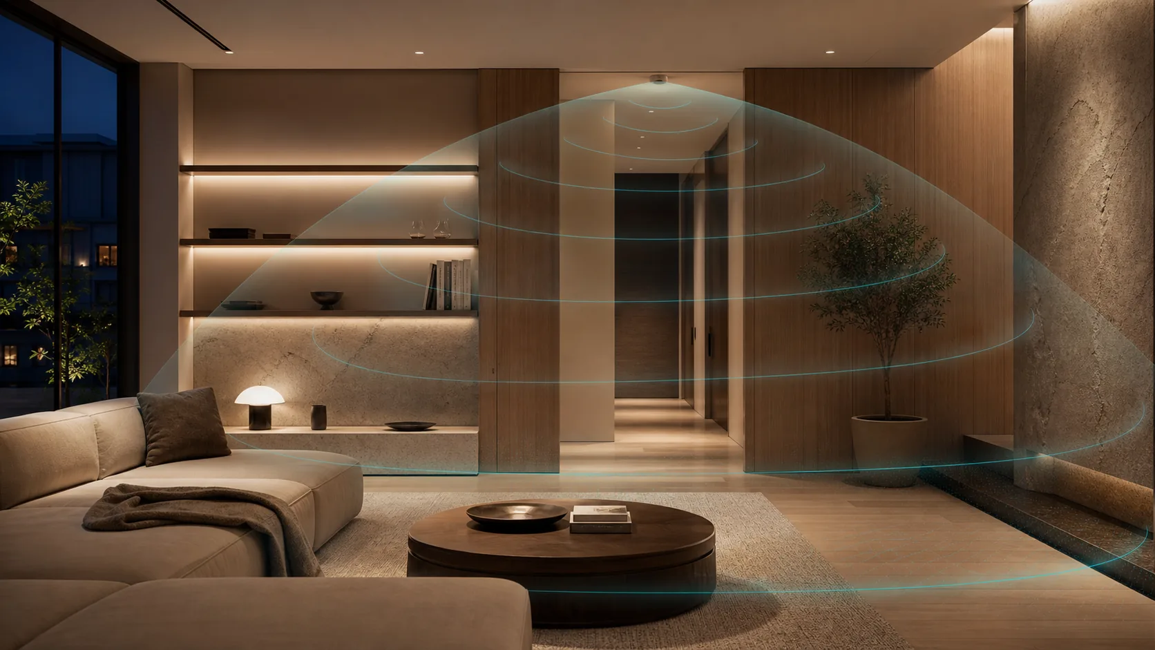
Mounting height is a design input, not a performance promise. It changes the geometry between a radar module and the target scene, but it does not describe the entire sensing outcome. Mounting angle, target zone, enclosure, nearby materials, background motion, host logic, and commissioning settings can be just as important.
The most useful installation discussion starts with a drawing. Mark the proposed module location, the area that should matter, the area that should not matter, the normal target path, and the expected mounting surface. A photo of the unfinished installation is often more valuable than a nominal range request because it reveals obstructions and reflectors that a data table cannot show.
Define the zone before setting a height
Do not begin with “what is the best height?” Begin with “what area should cause an event?” A doorway, desk cluster, hotel entry, ceiling zone, appliance front, or storage aisle can each have a different target geometry. The physical zone should include its boundaries and the conditions at its edges, not only its center.
Once that zone is clear, record the candidate height and angle. State whether the module faces downward, across a room, through an enclosure window, or toward a moving target path. Also record nearby metal, large glass surfaces, doors, fans, conveyors, water fixtures, or other moving equipment. These are engineering constraints to evaluate, not reasons to assume that a particular placement will fail or succeed.
Treat the enclosure as part of the RF system
If the module is installed inside a finished product, the enclosure location and material stack-up must be part of the review. Plastic thickness, cosmetic coatings, ribs, fasteners, cable routing, nearby electronics, and the clearance around the antenna region can alter the installed situation. A late enclosure change can invalidate an otherwise sensible prototype result.
Give the engineering team the mechanical envelope early, even if it is only a rough CAD snapshot. When the enclosure cannot change, test the module where it will actually live rather than first proving it in open air and treating that result as the final system behavior.
Build a small installation matrix
A practical validation plan uses a few representative conditions rather than one “coverage” walk-through. Include the intended target condition, likely background movement, zone edges, empty-scene behavior, the expected control response, and the configuration or firmware revision used for the test. Repeat each relevant condition after a mounting, enclosure, or logic change.
For ceiling and high-mount projects, include heights that represent the planned deployment rather than only a convenient bench height. For wall or appliance projects, include the intended user approach angle and normal surrounding activity. The point is to compare like with like and capture why a configuration was accepted.
Make commissioning traceable
Record the physical mounting position, angle, interface configuration, host firmware revision, and validation date. This gives a production or field team a reference when the finished product behaves differently after a mechanical or software change. It also protects the project from treating a successful sample result as an undocumented commitment for every installation.
Use YiRadar’s integration validation checklist alongside the actual installation drawing. For an initial candidate discussion, YR-DP101H, YR-DPL112P, and YR-RSC2411-A can be reviewed against the project conditions through the engineering contact route.
Ready to apply this?
Bring the project conditions to an engineer.
Module selection, final integration, and commercial terms are reviewed against the actual installation and host system.